|
|
|
|
|


I'm Online Chat Now
Certification


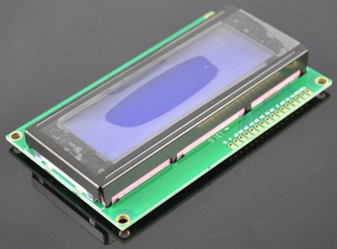
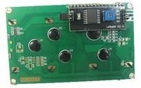
2004A 20x4 5V Character LCD Display Module for Arduino SPLC780 Controller Blue Backlight
|
Product Details:
Payment & Shipping Terms:
|

Detailed Product Description
| Working Temp: | -20~70℃ | Weight: | 80g |
|---|---|---|---|
| Highlight: | arduino bluetooth module,Ultrasonic Module |
||
2004A 20x4 5V Character LCD Display Module for Arduino SPLC780 Controller Blue Backlight
Specifications
1. Low Prices Direct From Factory Suppliers.
2.High Quality With Global Standards.
Description:
Use your solderless breadboard and wire jumpers to make these connections:
|
LCD Pin |
Connect to |
|
1 (VSS) |
GND pin* |
|
2 (VDD) |
+ 5v pin |
|
3 (contrast) |
Resistor or potentiometer to GND pin* |
|
4 RS |
pin 12 |
|
5 R/W |
pin 11 |
|
6 Enable |
pin 10 |
|
7 No connection |
|
|
8 No connection |
|
|
9 No connection |
|
|
10 No connection |
|
|
11 (Data 4) |
pin 5 |
|
12 (Data 5) |
pin 4 |
|
13 (Data 6) |
pin 3 |
|
14 (Data 7) |
pin 2 |
|
15 Backlight + |
Resistor to pin 13** |
|
16 Backlight GND |
GND pin* |
*Use a breadboard rail to make multiple connections to the GND pin for Arduino
*For potentiometer connection, use the potentiometer's center pin and either of the other pins to make the connection from LCD pin 3 to Arduino GND
** A current limiting resistor or potentiometer (40 Ohm minimum) should be used to avoid excessive current. It should look something like this:
Software
Here is the driver code:/* ------------------------------------------------------------------------------- */
// character LCD example code
// www.hacktronics.com
#include <LiquidCrystal.h>
// Connections:
// rs (LCD pin 4) to Arduino pin 12
// rw (LCD pin 5) to Arduino pin 11
// enable (LCD pin 6) to Arduino pin 10
// LCD pin 15 to Arduino pin 13
// LCD pins d4, d5, d6, d7 to Arduino pins 5, 4, 3, 2
LiquidCrystal lcd(12, 11, 10, 5, 4, 3, 2);
int backLight = 13; // pin 13 will control the backlight
void setup()
{
pinMode(backLight, OUTPUT);
digitalWrite(backLight, HIGH); // turn backlight on. Replace 'HIGH' with 'LOW' to turn it off.
lcd.begin(20,4); // columns, rows. use 16,2 for a 16x2 LCD, etc.
lcd.clear(); // start with a blank screen
lcd.setCursor(0,0); // set cursor to column 0, row 0 (the first row)
lcd.print("Hello, World"); // change this text to whatever you like. keep it clean.
lcd.setCursor(0,1); // set cursor to column 0, row 1
lcd.print("keyes");
// if you have a 4 row LCD, uncomment these lines to write to the bottom rows
// and change the lcd.begin() statement above.
//lcd.setCursor(0,2); // set cursor to column 0, row 2
//lcd.print("Row 3");
//lcd.setCursor(0,3); // set cursor to column 0, row 3
//lcd.print("Row 4");
}
void loop()
{
}
/* ------------------------------------------------------------------------------- */
You will now have a folder called LCD_example
Start the Arduino software and load the example program by clicking File->Sketchbook->Open
Navigate to the LCD_example folder and select the ?LCD_example.pde? file.
Transfer the program to your Arduino by clicking the ?Upload to I/O board? button. After uploading, on the LCD you should see:
Hello, World
PHOTOS:
![]()
![]()
Contact Details
China Professional Online Marketplace
Tel: +86-755-29858730~305
Send your inquiry directly to us
More Character LCD Display
-
40*4 Character LCD display
-
Mini Long Range Wireless Video Transmitter LCD Display COFDM UAV Sender
-
65" Multimedia lcd monitor outdoor display WIFI / 3G / bluetooth business for advertising
-
Indoor LCD Digital Temperature & Humidity Meter Environmental Testing Equipment Multi-function
-
LCD High Secure POS Pin Pad For Inputting Password Without Card Reader
-
Digital Display Plastic Thermal Deformation Vicat Softening Point Plastic Testing Equipment